| SYSCAD - CAD for metal construction |
|
Sheet metal |
Attachment details > Sheet metal |
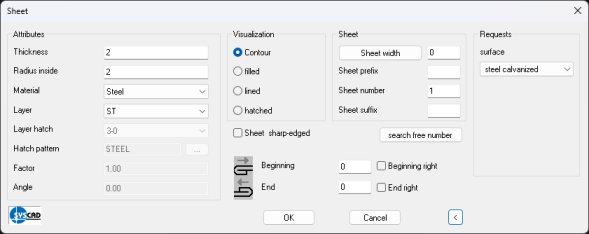
Drawing of any sheet metal contour with a polyline with arbitrary wall thickness and inner and outer radius. The sheet metal contours are adjustable via double-click or via moving the grips.
Enter the parameters into this dialog box and define the first point by clicking into your drawing. It could be helpful to use OSNAP. The coordinates of the second point can be determined by using relative coordinate input (@) or by clicking onto a point in your drawing. Define a third point afterwards to determine the direction for drawing the wall thickness of the sheet metal. Procedure analogously to membrane.
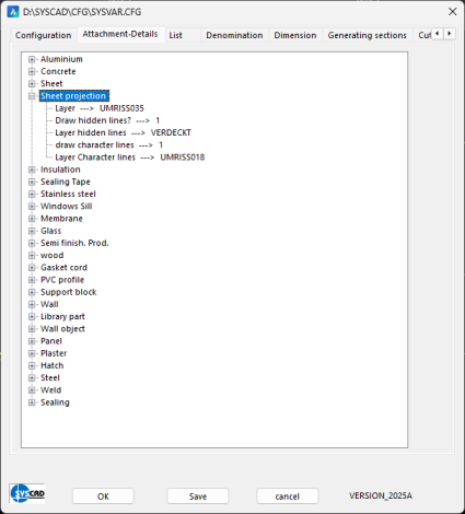
The preferred values for radius and thickness can be defined in the dialog box SYSCAD-Variable / Attachment-Details / Sheet for each sheet metal type.
Draw a sheet the inner or outer sheet contour of the sandwich panel with the correct thickness with the normal SHEET command. In this example 0.5mm Command: Choose sheet: Click onto the sheet
Point for direction or ENTER for OK: Click with the left mouse button to change the direction
Automatic measurement of the sheets: Three variants are available for this purpose. "Sheet dimensioning" command Command "Sheet dimensioning complete" "Sheet dimensioning inside" command Activate the command
If necessary, move the dimensions using the AutoCAD/BricsCAD handles of the dimension objects.
This command creates a sharp-edged auxiliary contour of the selected sheet metal Sheet developed view: Using this command, you get the sheet development (outer surface) of the sheet metal with the defined length. Activate the command
The outer surface (developed view) is calculated by means of the stretched lengt. The calculation with neutral axis is not used yet. You can join two sheet metals. To do so, activate the function "Sheet join"
Separate sheets: Separate sheets by first clicking the sheet and then the desired separation pointusing the "Separate sheet" function Sheet surface: This command automatically draws a polyline of the fold line of a sheet metal. Activate the command
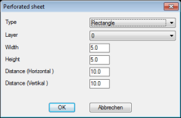
This option is available to create rectangular or circular patterns in a closed contour in the same way as a hatch.
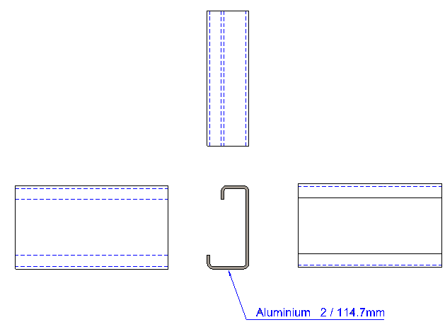
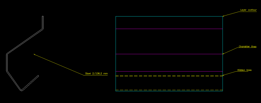
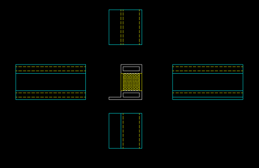
Projection of sheet metal edges You can use this command to automatically draw the side view (from the left) or the top view (from below) of sheets. Activate the command
You can change the display under SYSCAD variables / Attachment details / Sheet.
Projection of sheet metal edges
With the function "Sheet from polyline" you create sheets from the line segments of a polyline. Offset sheet: With the function "Offset sheet" you create sheets as a duplication of existing sheets or foils. Enter the desired distance in the following dialogue box. Move the virtually displayed contour to the desired side of the sheet with the left mouse button and confirm with the right mouse button. Now you can draw the sheet contour on any side of the virtual contour using the red arrow. Define the sheet metal contour in the dialogue box that now appears.
Command: "Open Config Files
Ribbon -> SYSCAD20XX -> Config
The "Insert point"
|