Dimension face width


Dimension face width |
|
This command is used to dimension the face widths of your SYSCAD constructions. The mode of operation is similar to the centre line dimensioning. Command: Dimensioning face width from point:(P1) to point: (P2) horizontal dimensioning Origin of extension line : (P3) Dimension line location : (P4)
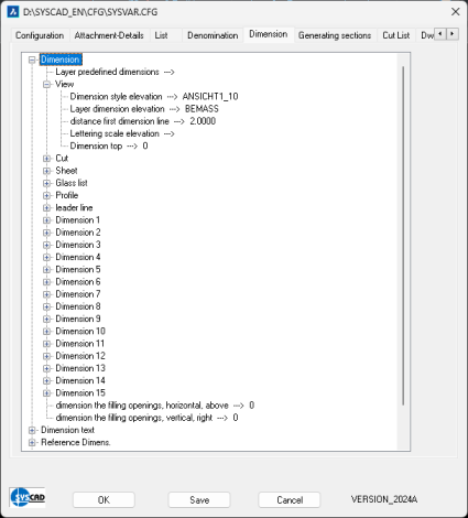
The dimension style for the elevation can be defined in the SYSCAD-Variable / Dimension / Dimension / View:
In case you draw your elevation on scale of 1:1 and display it 1:10 in general, it is advisable to assign the style ANSICHT1_10, defined in the prototype drawing SYSCAD.DWT, to the variable DIMENSION STYLE ELEVATION. All dimensions of face widths are drawn at the pre-defined layer and in style ANSICHT1_10. |