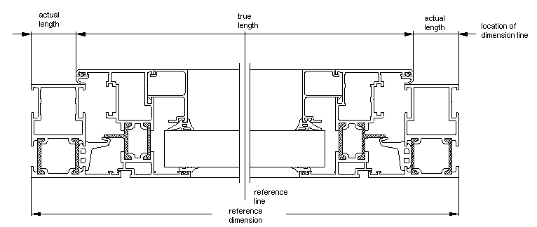
Example for reference dimension


Example for reference dimension |
|
|
Calling the program when there has no interrupted sectional view been defined yet, the first point of the reference dimension is requested by the program.
For multiple interrupted sectional views a reference dimension is required for each interrupted sectional view. The location of the reference point "Bz1" and "Bz2" determines the alignment of the reference line for the dimensioning (see example next page). First point : Bz1 second point : Bz2 As reference points for the dimensioning you could determine the outer dimension and the centre line distance as well as vent dimension, glass dimension or every other point you like. Determine reference line: Length and location of the reference line is defined by diagonal point determination of cut lines and the location of the dimension line. (presetting OSNAP <endpoint> ) First point : Ab1 diagonal corner : Ab2 If there are no cut lines in the drawing, the points are freely selectable.
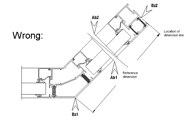
Location of reference points:
The example demonstrates a point determination for a reference dimension in a slope. The reference points "Bz1" and "Bz2" determine the direction of the reference line, that is used to position the dimensions. It also applies to horizontal or vertical dimensions. Define further reference dimensions (Y/N) <N> When confirming the presetting <N> with Ref. lines : Show/Add/Delete/Alter Ref. dimension : Factor/Alter dim./Dimension/Exit <EXIT> When entering "Y" the next reference dimension can be determined as described above. REF. DIMENSION : Factor(1)/Alter dim./Dimension/Exit <EXIT> Factor: The dimensioning factor is determined by clicking on a block or a dimension. The current value is set to "DIMLFAC". The variable "DIMLFAC" affects all linear dimensions, whose distances are multiplied by the factor and specified as measure (dimension text). New Command: "Change reference dimension factor". Alter dimension: This option is used to alter dimensions related to an interrupted sectional view. All dimensions crossed by the reference line are recalculated after alteration.
A dimensional change over interruptions is not possible!!
In case the sectional drawing contains for example two interrupted sectional views and the total dimension across both interrupted sectional views should be altered, it is necessary to enter the new value for reference dimension 1 and reference dimension 2. In case you stretch the reference dimensions, it is necessary to recalculate the reference dimension with Alter dim. Otherwise errors will occur when further dimensioning with reference dimensions. Please also see example "Reference dimension" in chapter 11. Dimension: It is used to dimension a manually generated sectional drawing. It is also used to supplement program generated sectional drawings. OSNAP <Endpoint> as presetting. In case the reference line is crossed by the point definition of the extension line, the true length is determined in consideration of the reference dimension. In case the reference line is not crossed when dimensioning, the real length is displayed. Exit: Leave the program: Presetting <EXIT> confirm with
REFERENCE LINES : Show/Add/Delete/Alter Show: This controlling function can be used to visualize the location of all reference lines within the screen sector.
Add: This option is used to add reference dimensions to sectional drawings. The definition is according to the description in Determine reference dimension: and Determine reference line: . Apportion evenly: This option is used to adapt desired dimensions. The remaining dimensions are adjusted accordingly. Proceed as follows: •activate the command "Reference dimension". •Let the program calculate the correct DIM.FACTOR, whit clicking on a SYSCAD block or a correct dimensioning. •Call ALTER DIM and select a dimension crossing several interrupted sectional views. Enter the desired value (DO NOT CONFIRM!! If you need equal values, please enter again.) •Select APPORTION EVENLY and click on the desired dimensions. •READY Delete: It is used to delete reference lines in the drawing. You can delete single or all reference lines. The existing dimensioning is not affected. Alter: When selecting the reference line and clicking to a point, the length of the reference line is altered.
|