| SYSCAD - CAD for metal construction |
|
Indication of altitude |
|
The programme is used to create reference dimensions, the so-called "Indication of altitude". The indication. of altitude always refers to a reference point in your view or in the section. We call this point the BASE POINT. All other elevation coordinates refer to this BASE POINT. You can of course define several BASE POINTS in your drawing and thus enter height coordinates in the view and in the section. There are 2 types of commands available to you:
Indication of altitude (block): For creating vertical reference dimensions, with blocks. Certain attributes are assigned to the blocks Advantages: •Handling is simpler, more modern and more streamlined thanks to the block logic. •The height marks can be easily copied and moved. Disadvantage: •Horizontal dimensioning is not possible, so no coordinate dimensioning can be carried out.
Indication of altitude (group): For creating vertical and horizontal reference dimensions, as a group. Advantage: •The dimensioning is possible horizontally and vertically. A coordinate dimensioning can be created. Disadvantage: •Due to the representation as a group, the command: "Update dimensions" must be activated after each "move" . •Copying of altitude values is not possible.
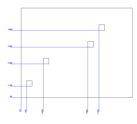
Example (possible with both commands):
In this image you can see a height dimensioning. The lowest dimensioning serves as the basis (here with the height value 0). All other dimensions can be placed as required by the user. The dimensions are calculated automatically by the programme.
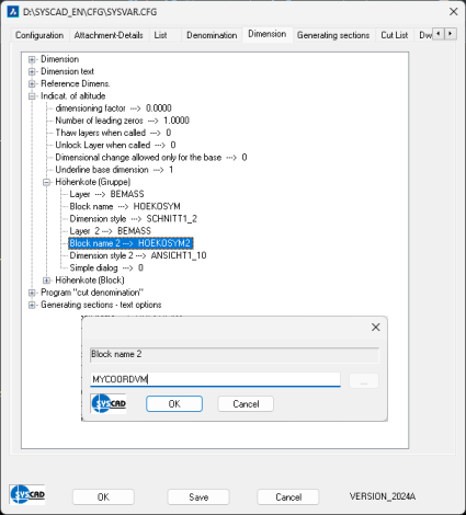
Coordinate measurements are possible with the command: "Indication of altitude (group)" By using an elevation block that consists only of the dimension number, coordinate dimensions are also possible:
The generation of the coordinate dimensioning is carried out in the same way as for the height grades.
|