| SYSCAD - CAD for metal construction |
|
Elevation from centre line grid |
Generating sections > Centre line grid > Elevation from centre line grid |
The function "Elevation from centre line grid" generates complete elevations from a centre line grid or any subsidiary lines. The grid of subsidiary lines must be a closed contour. It can consist of straight lines or polylines at any layer. The inner contour needs to run vertically or horizontally. Example: Draw the following grid.
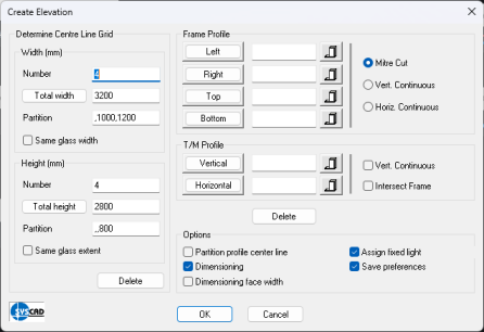
Call the command "Elevation from centre line grid". Enter the profile numbers into the dialog box showing up now or click the corresponding buttons for a graphical selection of profiles.
The result looks like this:
You may process this elevation with the following commands, change fillings etc. Please note, that the outer profiles are drawn at the outside contour of the grid. The inner profiles are drawn at the centre lines. Move the subsidiary lines accordingly. Use the command PROFILE ADAPTATION from the OPTIONS group to change the profile situation. From version 2000.11 you have the possibility to position the outer profiles at the centre lines too. To do so please activate the button "partition profile center line". |