| SYSCAD - CAD for metal construction |
|
Wall connection |
Generating sections > Wall connection / Add-on package |
The program "Wall connection / Add-on package / Additional parts / Profile completion" enables the calculation of customized wall connections/details with system parts and non-system parts. The used blocks are inserted automatically into the sections of your elevation. 1. Step: Defining the attachment detail: !! Important for wall connection, add-on package and profile completion !! First of all draw your attachment detail (scale 1:1). Save it to a directory with an existing SYSCAD Search path. (see dialog box SYSCAD-Variable / DWG Search Path). Always draw the attachment details horizontally and from the right in scale 1:1. The program "Wall connection"
Afterwards add this wall connection to your database. Use the program "Wall connection def."
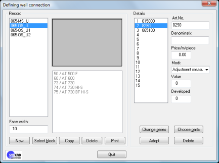
Create a new record using the NEW button. Here, it was named 065_OS_U. The face width was defined with 10. - SELECT BLOCK uses a block that has been already inserted into the drawing as a basis. The parts of the block are determined automatically. - COPY duplicates existing records. - DELETE removes redundant entries from the database. - PRINT prepares a list of the accessory parts used in your wall connection. Hint: Always print this information to keep track of the defined wall connections. Click on the first free entry of the list box DETAILS (with an empty list box always click on 1), and enter the accessory parts. In case you enter a system part, the fields DENOMINATION and PRICE are completed automatically. With non-system parts, these parameters are to be entered by you. Hint: Accustom yourself an uniform style for the denomination of the accessory parts. So the CUT LISTs are easier to understand. Select from the following variations in the field MODI: - Adjustment dimension: the dimensions taken from the elevation are reduced or increased about this value. - Absolute dimension: Entering a dimension, that is independent of the length of the accessory parts in the elevation. - Quantity / meter: The entered values are multiplied with the length. - Quantity: longitudinal-independent number of number of parts To save the data record for the several accessory parts press the ADOPT button. With CHOOSE SERIES it is possible to assign up to 10 series to the wall connection. So this special wall connection is only displayed with elements of the assigned series. The function CHOOSE PARTS assigns different parts (profiles, membranes, sheet metals, insulation, norm parts..) to the selected wall connection. Leave the dialog box with QUIT.
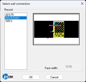
2. Step: Assigning Wall connection / additional package: Procedure: "Wall connection" Call the command "Wall connection" Select the wall connection for every side of the elevation afterwards. Please make sure, that the active side of the elevation is highlighted and printed dashed. (In case the following dialog box overlaps the elevation, it is possible to move it).
|