| SYSCAD - CAD for metal construction |
|
Frame / Mullion |
Generating sections > Frame / Mullion |
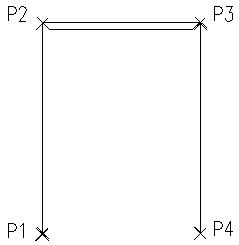
The program In case the point definition is performed clockwise, the definition points are at the outer profile edge of the framework contour. Counterclockwise the definition points are accordingly at the inner profile edge. Define the outer corners of frame by clicking at the screen (dimension via coordinates shown in the menu bar) or via entering relative coordinates (@). Attention! The command Select a profile from the preselected series and determine the first distance (P1 P2). The selected profile (for example 510102) appears as pre-selection in the menu line. With a right mouse click you get the options. The program To select an option or a variable, type in the corresponding abbreviation (capital letter), e.g. "C" for "CLOSE" or just select it in the screen menu.
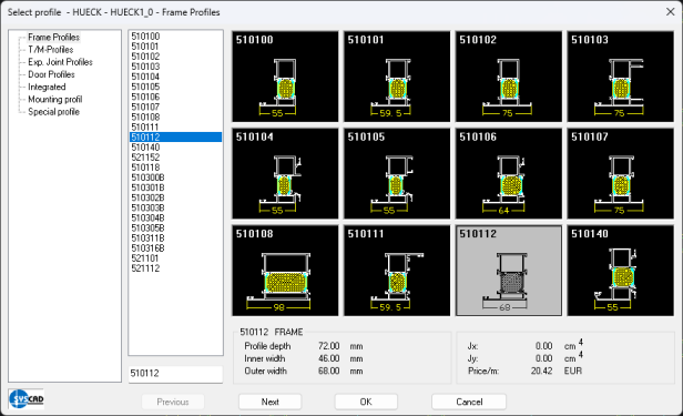
Attention! No check on static feasibility of the chosen profiles is carried out. Options of the program Close: Pick the option "CLOSE" at the inquiry "to point" to connected the current point of the frame with the origin. Open: With an open frame construction, for example with doors, select the option "OPEN" at the inquiry "to point." Open + Aux: This option is to draw an auxiliary profile at the open side of the profile contour in order to subsequently define the FILLING with a click into the opening. Back: This option offers the possibility to delete the frame segment drawn last without interrupting the program. Several "Z" delete in logical sequence backwards. Profile <510102>: Pick the desired profile for the next segment. The last used profile is still pre-selected.
The selected profile is saved as a variable and is used as a presetting for the next frame segments. When changing the profile, please enter a "P" at the inquiry "to point" or select PROFILE from the context menu. The presetting is used for the next segments. In case, the profile widths are different with a profile change and the presetting of the corner connection is "mitre joint", the following dialog box appears:
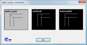
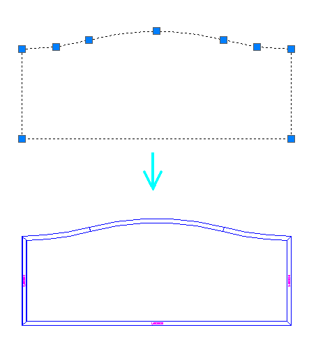
Corner conn. < MITRE JOINT>: The standard presetting of the corner connection is MITRE JOINT. The presetting applies to the entire frame if the variable is not changed. If the corner connection should be different at the framework, select "Corner Conn." from the context menu at the inquiry "to point" . The dialog box "Select corner connection" is shown. Select a variation by means of the cross hairs. The variable <Mitre joint> is overwritten with new selection, e.g. "vertical". The new presetting (vertical) is used for all next corner connections until the variable is overwritten again. Under certain circumstances it could be helpful to work with one corner connection and change particular corner connection with "Alter corner connection" in the pulldown menu GENER. SECTIONS / OPTIONS. The first two points determine the end of the profile. The third point determines the middle of the arch.
The profiles and its calculated lengths are listed in the parts list. Fillings are currently not possible as well as the automatic denomination of the curved profiles. NEW with SYSCAD 2009: It is possible to enter customized order numbers into the text field of the dialog box. It is the dialog box to define additional items. These Additional items are drawn like standard SYSCAD profiles. The profiles can be cut and are listed in the parts list.
Draw the definition line for your profiles with the command polyline. The command
These SYSCAD profiles can be used as a boundary for fixed glazing, window infills, muntins, etc. SYSCAD creates the profiles with the ridge side in the direction of the polyline. This direction can be changed beforehand with the command PEDIT / Change direction. Subsequent rotation is not possible here. |