| SYSCAD - CAD for metal construction |
|
T/M-Profiles / Transom |
Generating sections > TM-Profile / Transom |
The program The position of the profile centre lines is determined by a point definition via OSNAP, via the program (centre) or by the (REF. point) definition. Note: With FACADE series the command TRANSOM/MULLION is often misunderstood . The command is used to determine inner profiles whatever profile (transom or mullion profiles) you put in. Determination of profile centre line via OSNAP After the Determination of profile centre line via MEASURE INPUT A reference point (P1) is determined by means of (REF. point) to input of the centre line distances.
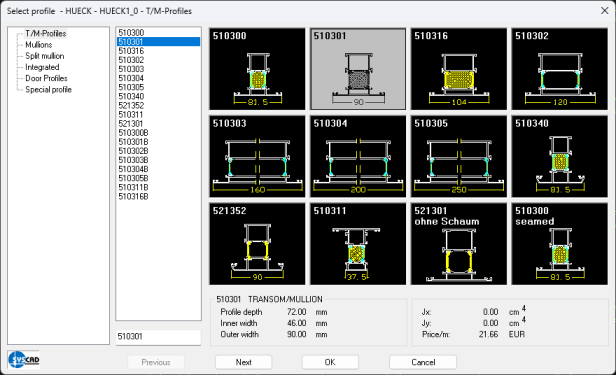
With the message "Transom/mullion profile from point <Next>" select the line to start drawing the T/M-PROFILES from. With the inquiry "to line <PERPENDICULAR> " select a line to end drawing the T/M-PROFILES with. The OSNAP < > in angle brackets is predefined. The dialog box "T/M-PROFILES" is displayed now. Click into a field for profile selection.
After the profile selection the inquiry " Move or <RETURN> to accept". If you select the option "Move", the T/M-profile is shifted by a 1/2 face width at a time. Confirm the desired position with In case the point input of the T/M-profile centre line coincides with two profiles and the option "Move" is activated, an inquiry regarding a centre line misalignment is displayed: 1/2 face width outside 54.0 (e.g. for 620320) 1/2 face width inside 30.0 < 54.0 > The advantage with shifting the face width inside is, that the interior chambers of the profiles converge in the corner point. Accept the position with End <T/M-profile> profile <620320> Transom/mullion profile from point Profile <620320>: The selected profile is saved as a variable and is the default for all following T/M-profiles. If you want to use different profiles, click on "profile" in the screen menu. For the profile selection the slide " T/M-PROFILES " is displayed. End of <T/M-PROFILE>: The input "E" or Intersecting T/M-PROFILES: Profiles, that are intersected by the run of a T/M-profile ("T/M-profile from point" (P1) "to line"), are divided automatically by the program (see example). In case the fields are already filled with fixed lights, the division is applied to profiles and glazing. T/M-PROFILES across insert elements (doors or windows) are not possible.
Please note: SYSCAD does not verifies the selected profiles regarding static feasibility.
Version 2000.13 offers a new command for drawing auxiliary T/M-profiles. It is to generate closed contours for fillings. Use this command to get a closed contour with doors to execute the command "Edit grid" NEW with SYSCAD 2009: It is possible to enter customized order numbers into the text field of the dialog box. The dialog box for defining additional items is displayed. These "Additional parts"
|