SYSCAD - CAD for metal construction Start  back  next

3D View / BIM-Export

Generating sections > Cut list > 3D View / BIM-Export

Toolbar: SYSCAD Generating sections -> SYSFLY View -> 3D View

Ribbon: SYSCAD Gener. Sections -> Cut List -> 3D View


The command produces a copy of the elevation representing the profiles in 3D. Important: Please only use a copy of your drawing. After the use of ORBIT, AutoCAD causes some difficulties. See below...

The profiles of these 3D view can be dimensioned with the help of AutoCAD/BricsCAD functions to represent difficult cuts and processing.

kap5_48

The problem is that AutoCAD overwrites the system variable TARGET while executing the ORBIT Command. Use the command "RESET TARGET" from the toolbox SYSCAD PROGRAMS to solve of the problem .

Text from the AutoCAD help:

This problem can occur if the system variable is set to something other than 0,0,0, the default value. When the variable is set to a non-zero value, the drawing limits May be interpreted incorrectly. The system variable changes when you use the DVIEW command. Once you use the DVIEW command to set a perspective view, this view of the drawing is used and interpreted ace if it is visible when looking through a camera pointed at a target point. This is the equivalent of the image of the drawing ace it would be projected on a view flat perpendicular to the direction the camera is pointing. When you plot the drawing, this projected image is plotted. The display, extents, and window are defined for this projected image, but limits are only defined for the drawing, necessary the projected image of the drawing.


BIM Export

Toolbar: SYSCAD Generating sections -> SYSFLY View -> BIM-Export

Ribbon: SYSCAD Gener. Sections -> Cut List -> BIM-Export


The command BIM-Export creates a 3D-model of your SYSCAD-elevation into a seperate drawing.   Profile and fillings are created as simple 3D-Solids. Gaskets and glazing beads are not in the right shape.


BIM-Export


Change the layers to your needs. There is a template for this (SYSCAD_BIM_MAT.DWG)


- The value Subtract-Z-Offset is for moving the BIM-object into the Wall.


- The depth of the trigger body is defined with Subtract-Z-Depth.


- the distance to the wall could be defined with Subtract margin.


In the template SYSCAD_BIM_MAT.DWG are some materials defined and attached to one or more SYSCAD-Layer (MATERIALATTACH):


dialog_matanhang


The KGL_BIM_ADDEED function KGL_BIM_ADDEED allows to assign 3D blocks to 2D SYSCAD views.

dlg_bim_addeed1

SYSCAD 2D view


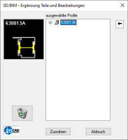
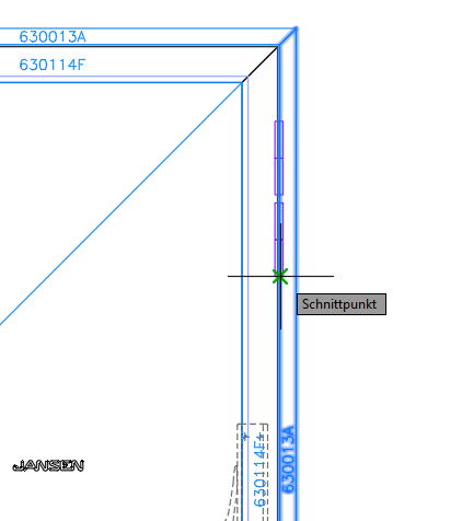
Start the command KGL_BIM_ADDEED kgl_bim_addeed_16


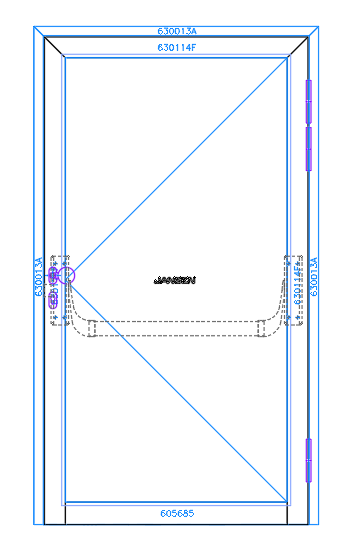
and select the desired profile to assign the 3D object. In this case, the right frame profile. The bands at the top and bottom are already assigned.


The 2nd band from the top is still missing.


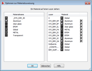
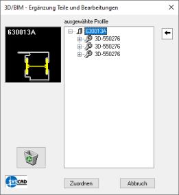
The following dialog appears:


dlg_bim_addeed2


Use the left mouse button to drag the sliding arrow dlg_bim_addeed2b to the desired profile. In this case just the right frame profile.

The file selection appears. Select the desired 3D block


In the drawing, define the assignment point of the desired block.

dlg_bim_addeed3

Here the intersection point of the 2D tape block with the profile edge.


This dialog box appears:
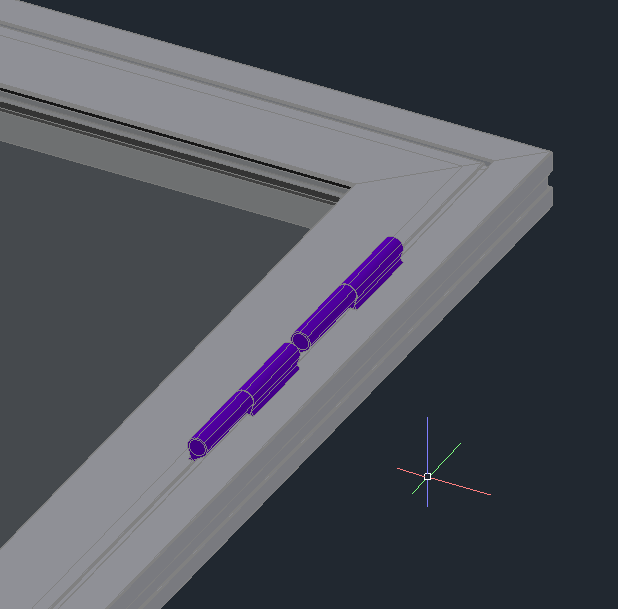
dlg_bim_addeed4

Click on "Assign


dlg_bim_addeed5

The result


In the SYSCAD variable the path to the 3D blocks for the search still has to be defined. SYSCAD VARIABLE -> LIST -> 3D-VIS/BIM -> User defined parts

dlg_bim_addeed6