| SYSCAD - CAD for metal construction |
|
Filling |
Generating sections > Filling > Filling |
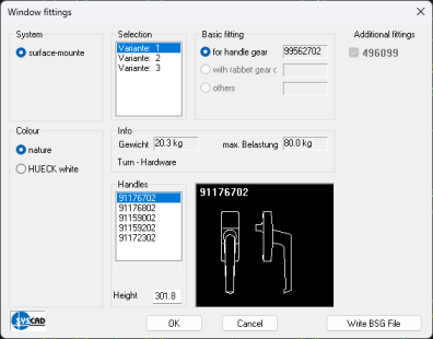
The "Filling" To determine a field just click into the field (determines the outer contour) or select the corners via OSNAP. The profile series of the FRAME is checked and the dialog box "Filling" is displayed. Please note: The program to the determine of the outer contour considers only profiles. If there is no closed contour around the selected point, the centre line grid (auxiliary lines) are included into the second search mode. The program "Filling" RETURN for end of filling Define first corner (bottom left) or select point in closed contour In the second level a filling type has already been selected. This version applies to all following openings, until you confirm once. You recognize the second level by means of the text output in the command line. In the following example FIXED LIGHT with the defined glass has been selected. To end the program "Filling" duly it is necessary to confirm twice. End of filling <fixed light> Glass dimension <22/5,12,5> Define first corner (bottom left) or select point in closed contour Filling types: Depending on the used profile supplier you are asked for the fittings. This option can be deactivated with the dialog box SYSCAD-Variable / Cut List. After defining for instance a window filling, the following dialog box appears:
New fittings can be defined in the "Special fittings" Note: If you change the elevation with AutoCAD/BricsCAD - commands (e.g. to stretch or scale), the fittings selection is not adapted automatically to the changed dimensions. In this case you need to delete the filling and redefine the respective fitting. You can also use the command "Change filling" from the command group OPTIONS to define a new fitting. Note: Since version 2000.06, you can also double-click the respective filling. |